IT Network Redundancy - Just Another Single Point of Failure (SPOF)? Trace by reverse engineering the Network logical packet flow to find out!
What is redundancy? Network redundancy attempts to reduce single point of failure (SPOF) by having two or more active-active, active-standby or hot standby components whenever possible. Most try for Active-active where both components are continuously active providing load balancing features and fail over to one another in the event of failure. The trouble is, sometimes two items are installed and operating, but when one fails, part or all of the service goes down. The reason is that despite having two components, logical dependencies having complex configuration require rigorous testing and high theory engineering. The result is that some just have double the dependencies at twice the cost producing a lower MTBF because of the multiple components - not to mention the support complexity. The key is rigid documentation and test labe case studies - resources most environments don't have access to. The video describes a visualization of a reverse engineered system tracing application packet flow showing that instead of one set of single points of failure... any of the redunanct componenets that might fail would bring all end user functions down.
Effective network documentation of network application flows and application characteristics uncover the truth about redundant components on your enterprise data center system architecture diagram. Wisely consider logical transaction and packet flow when preparing an IT disaster recovery plan - particularly when updating the plan for cloud spof disaster recovery and disaster recovery testing.
Network component redundancy requires the purchase of two of everything and makes the design and maintenance very complex. Are you getting what you think you paid for in both product and complexity costs? Sadly most redundant systems are either not operational because the redundant configuration engineering exceeds the staff's ability or it has flaws creating a worse set of dependencies than a single point of failure (SPOF) design would. By documenting your layer 2/3 environment well and superimposing application transaction steps thereon you can quickly see any flaws. The example is classic! Enjoy.
Complete Transcript:
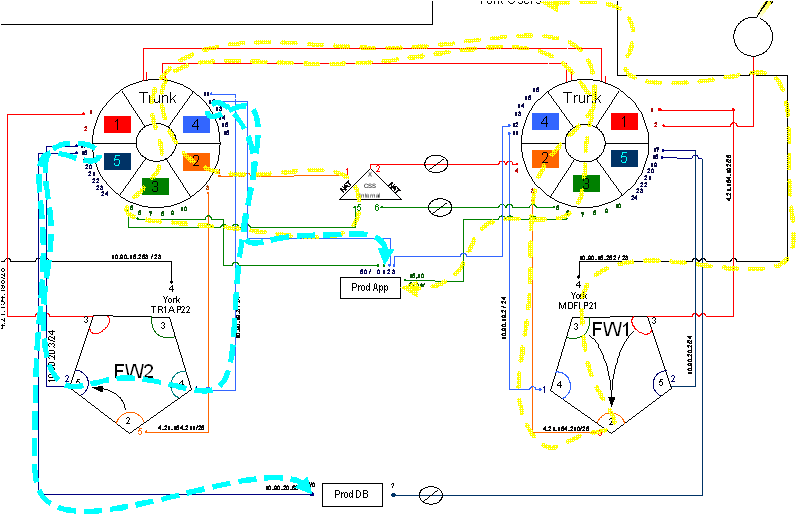
Speaker: Here's another one. You bought two of everything because management said, “what if that thing goes down?” Some non-technical auditor came in and said, “what if that goes down, that's really important, you ought to have two of those.” So we bought into this and we started buying two of everything. Well, when I go into an enterprise and I start documenting their system to troubleshoot a problem, and I do my layer two, layer three diagrams depicting layer two and layer three analysis of where a packet goes, step by step through an infrastructure by VLAN and by component. This starts to expose our dependencies logically. Now you can see that you have two of everything from a physical standpoint, but logically, the way that we configure it and how packets actually flow through it, is an important thing to also diagram. So I've diagramed for you, a very complex environment, where we have an application server right here and we have a database server right here. The application server is what serves up to the end users, the user interface, and the database server is where the application server goes to get all the data from for those particular transactions.
So let's start out here with the yellow line, the yellow brick road let's call it. We go down the yellow brick road here. We come into a firewall, into our application environment, and we come in on port three. We go on port two. We come around here, we go up to VLAN II on switch one. VLAN II on switch one needs to communicate with the device on VLAN II of switch two. SSo it goes across the trunk, comes over here, gets into VLAN II on switch two, goes into the content server on switch two and into the contents switch which load balances between all of our application servers. It comes through here, goes out VLAN III on the other side of the contents server, comes up and over and back through into VLAN III on switch one. Which then connects up to our applications server called Prod DB or Prod App. So, here we are, we've just gone from the user which is out here, through our firewall, out through our firewall, through both of our switches, through our content switch, back and forth across the trunk a couple of times, headed out and now we've finally got to our server. So are we dependent upon, for the initial transaction, what? This firewall, this switch, these trunk circuits, and this switch. Am I not correct?
Well, to complete the transaction, the Prod App server has to do a sequel query on the database over here down at Prod DB. So consequently it then sends out that goes into VLAN 4 on switch two, comes back out, goes into firewall interface four, comes over to interface five, goes back out, goes into the switch and back out of the switch on VLAN 5, and then heads to Prod DB. Now at least from my vantage point here, I've traced this logic to show that for this transaction to be successful, we have to have not only switch one, switch two, firewall one and firewall two. If any of those components were to go down, which is the reason why we have two of them, our user would not be successful. So until we basically take a look at and diagram layer one, layer two transactions into our applications and through those complex switches, we can't really see what's going on. So this sort of a process of knowing where your layer two and layer three information is, is very important.
Zero Tolerance: AI Pipelines, Robotics, and Beyond
The hidden single points of failure exposed in this analysis are no longer just a business continuity concern -- they are a safety and reliability concern for AI inference pipelines, robotics control loops, and crypto validator nodes. An AI agent making real-time decisions cannot tolerate a hidden SPOF that kills its database connection mid-query. A surgical robot receiving instructions over a network path with an undetected single point of failure is a liability. A blockchain validator that loses consensus because of a redundancy gap loses real money. The methodology of tracing layer-two and layer-three paths through every switch, firewall, and VLAN documented here is now mandatory for any infrastructure where downtime has consequences beyond inconvenience.
Redundancy validation requires the same wire-level proof it always has. NVIDIA DPUs capturing at 400 Gbps give engineers the visibility to map every path and confirm that failover actually works under load. Bill Alderson discusses how the convergence of AI, cybersecurity, crypto, robotics, and quantum is raising the stakes for infrastructure design on the Morpheus Cyber podcast.
1047